Analysis and Design of Analog Integrated Circuits

# Need for Current Mirrors in Microelectronics
- Bias circuits designed with current sources tend to be more insensitive to power-supply and temperature variations
- For small currents, they tend to have a smaller on-chip footprint compared to resistor based techniques
- As active loads, they provide high impedance, enabling high gain in voltage amplifiers
# 4.2 Simple Current Source
# Working principle of a Current Mirror
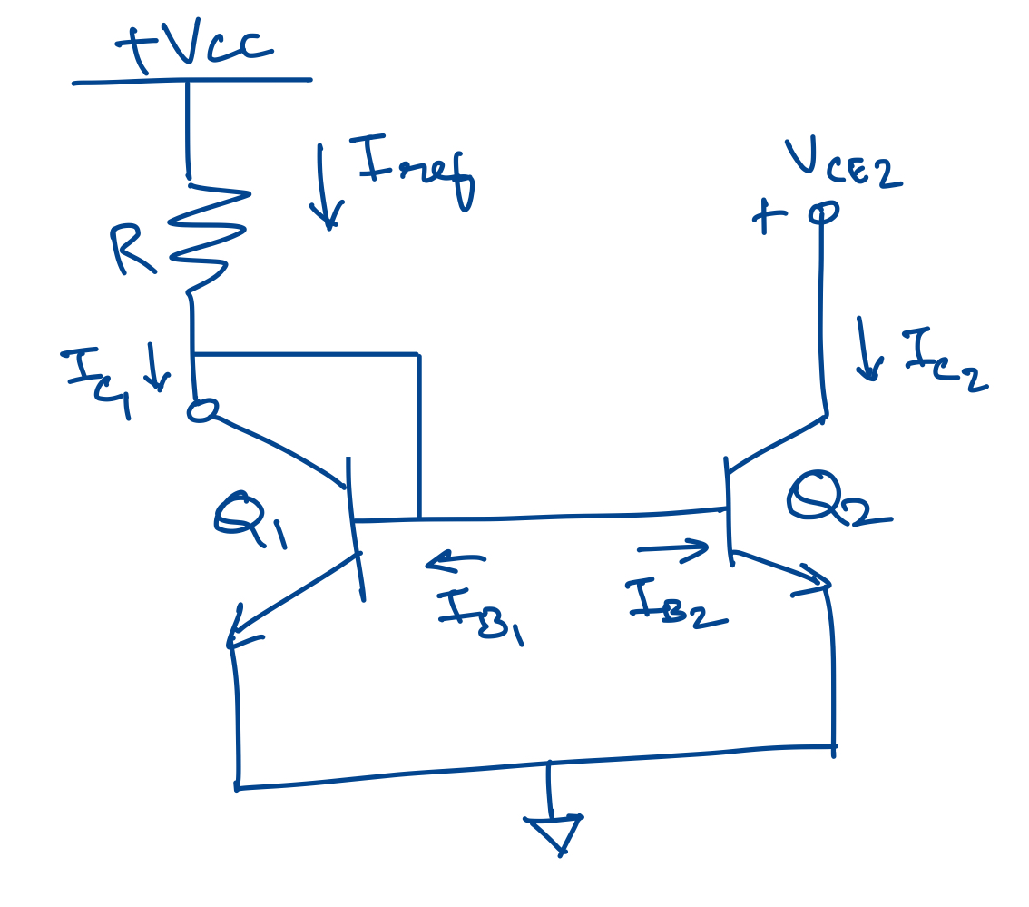
Transistor Q1 is diode-connected which means that the collector-base voltage is zero. Q1 and Q2 share the same base-emitter voltage. Assume that the output impedance of Q2 is infinite. The voltage to turn on transistor Q1 is $V_{BE(on)}$ .
If the transistors Q1 and Q2 are equal, $I_{c1} = I_{c2}$ and $I_{b1}=I_{b2}=I_{c1}/\beta_f$
Summing currents at the collector of Q1, $I_{ref} - I_{c1} -I_{b1} - I_{b2} = 0$
Substituting for $I_{b1}$ and $I_{b2}$, $I_{ref} - I_{c1}(1+2/\beta_f)=0$
or, $I_{c1} = I_{ref}/(1+2/\beta_f)$
If $\beta_f$ » 1, then $I_{c1}=I_{c2}=I_{ref}$
Hence, to refer the current back to the supply voltages, $$ I_{c2}= \frac{V_{ref} - V_{BE(on)}}{R} = I_{ref} $$ In general, Q1 need not be the same as Q2. If Q2 is twice the size of Q1, then $I_{c2}$ will be $2\times I_{c1}$. You can generate any current ratio this way. But for very large current ratios, Widlar current source is a better choice.
# Impact of finite output resistance on the working of a current mirror
# Thevenin voltage as a figure of merit for current source performance
# Improved current source with low-gain bipolar devices
# References
- Analysis and Design of Analog Integrated Circuits, 2nd ed, Paul Gray and Robert Meyer, 1976.