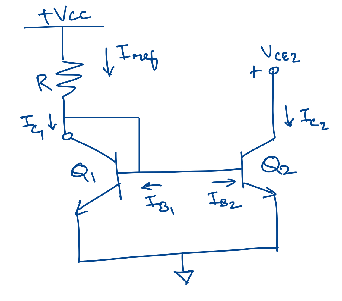
Working principle of a Current Mirror
A Current Mirror copies the golden reference current $I_{ref}$ generated by a Band Gap Reference circuit.
# Circuit Diagram

# Explanation
- The purpose of transistor Q1 is to generate an output voltage at its base that is proportional to the input current at the collector. In a MOS Transistor, a gate voltage will be generated proportional to the drain current. The reference current is converted to a voltage.
- The purpose of transistor Q2 is to use the generated voltage at its base/gate, to create a replica current of $I_{ref}$ at its collector/drain.
- If the properties of Q1 and Q2 are exactly the same, an identical current is copied or mirrored to the output transistor.
# Equations
Transistor Q1 is diode-connected which means that the collector-base voltage is zero. Q1 and Q2 share the same base-emitter voltage. Assume that the output impedance of Q2 is infinite. The voltage to turn on transistor Q1 is $V_{BE(on)}$ .
If the transistors Q1 and Q2 are equal, $I_{c1} = I_{c2}$ and $I_{b1}=I_{b2}=I_{c1}/\beta_f$
Summing currents at the collector of Q1, $I_{ref} - I_{c1} -I_{b1} - I_{b2} = 0$
Substituting for $I_{b1}$ and $I_{b2}$, $I_{ref} - I_{c1}(1+2/\beta_f)=0$
or, $I_{c1} = I_{ref}/(1+2/\beta_f)$
If $\beta_f$ » 1, then $I_{c1}=I_{c2}=I_{ref}$
Hence, to refer the current back to the supply voltages, $$ I_{c2}= \frac{V_{ref} - V_{BE(on)}}{R} = I_{ref} $$